Sales
- Details
- Written by: zhang
- Category: Sales
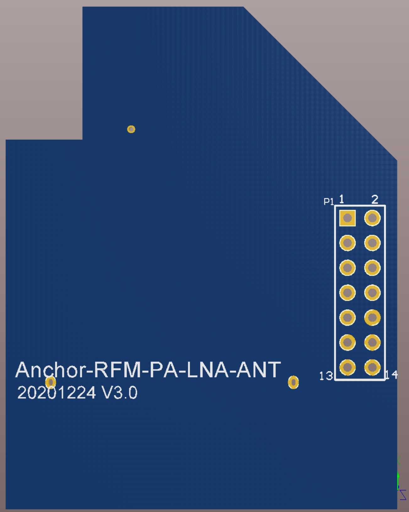
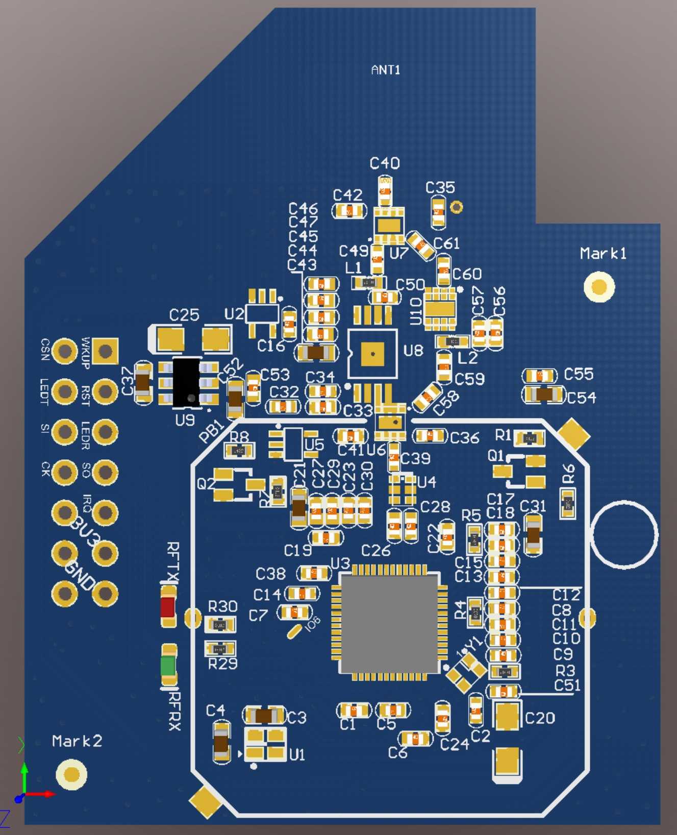
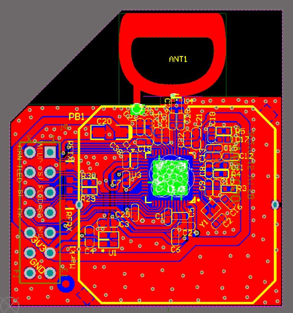
UWB Module Anchor-RFM-PA-LNA-ANT Circuit Diagram and PCB - Price: $450 USD
The module adds LNA and PA, and the communication distance is greatly increased. The module uses a PCB antenna and uses pin headers to connect to the anchor chassis. Can be adapted to indoor version anchors A1102P and A1106P.
We have tested that when using the 850K rate, the communication distance is more than 800 meters, and it should be further. Due to limited conditions, we did not test longer distances.
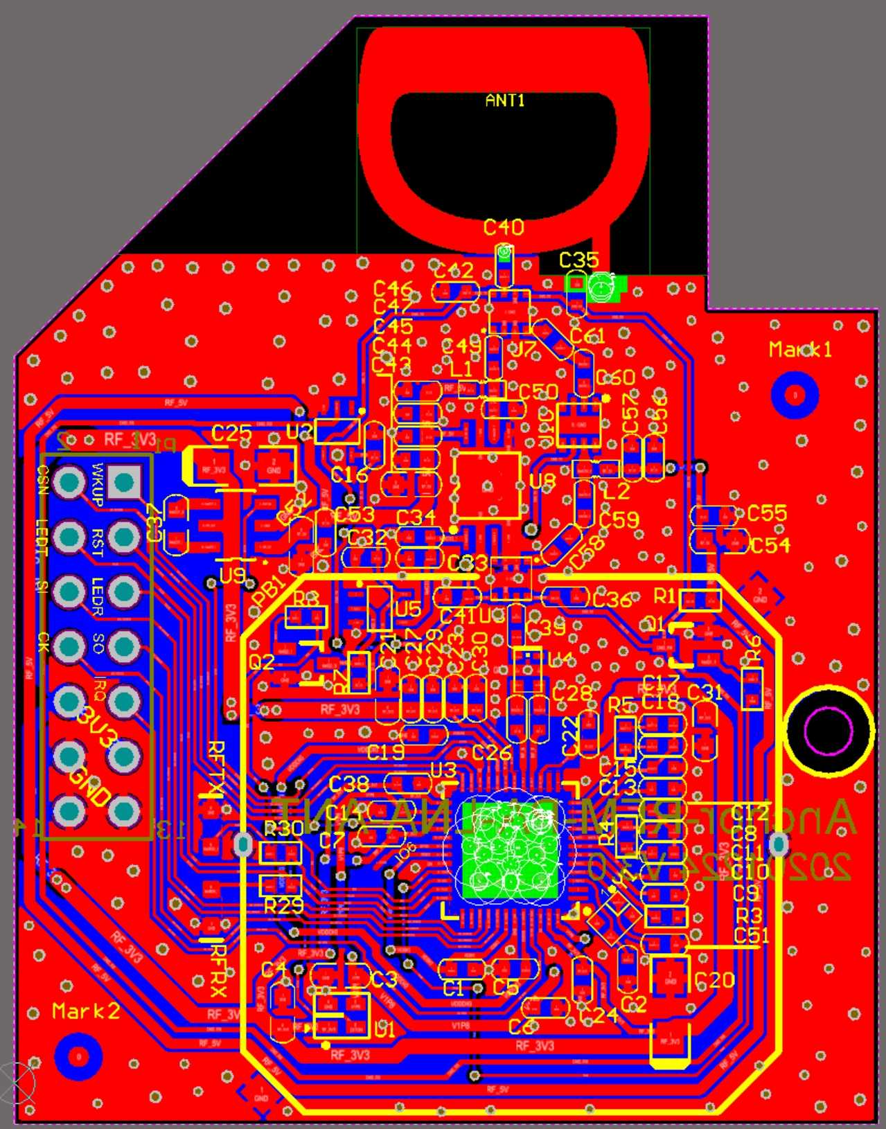
This module is sold with an indoor version of the anchor. Its specifications are basically the same as the UM2000 module. The difference is that one is a PCB antenna and the other uses an SMA external antenna.
Click here to download UM2000 specification manual V1.1.pdf for reference.
Some students may wonder why the module circuit is more expensive than the anchor backplane circuit?
Because of the difficulty! Hardware engineers know that in most cases, digital circuits are simpler than analog circuits.
Although we have modified the chassis of the single network port anchor dozens of times, the changes are all in details. It cannot be said to be worthless, but it is not strictly necessary.
In the early days, in order to reduce the difficulty of research and development, we always used the original UWB module. As the product matured and we hoped to reduce production costs, we decided to develop our own UWB module. The difficulty in developing UWB modules mainly lies in wiring. The wiring of the RF circuit is not just about impedance matching. This has always been a technical job, which requires not only theoretical support but also empirical support. We tried it many times before we got a satisfactory result. You can think about it, how long does it take a qualified engineer who is proficient in RF wiring to figure this thing out? How much salary are you going to pay him? For this price, it's just free of charge.
In the past, after we successfully developed a module without LNA/PA, we started to develop a module with LNA/PA. After all, the coverage area is wide, we can save a lot of anchors, and the total cost of the project can be reduced a lot. But it has always failed. I also bought several finished modules with LNA/PA from TAOBAO for testing. I found that the effect was not very good and the coverage did not increase as much as expected. We also tried using a separate LNA/PA to connect between the antenna and the module, but the effect was not effective either. After many failures and overcoming many pitfalls, I finally achieved a satisfactory result.
If your product has taken shape and is even on sale, then you must be very concerned about coverage. Adding LNA/PA is the only way to solve the problem of coverage .
- Details
- Written by: zhang
- Category: Sales
UWB Location Dual Network Port Outdoor Anchor A1108 Baseboard Circuit Diagram and PCB Diagram - Price: $300
A1108 is based on the dual network port anchor A1106P. It adds a high-brightness LED light according to the characteristics of the outdoor environment.
Like the A1106P, there are network switch chips and POE power supply chips, which can connect multiple anchors in a series to save wiring costs and POE switch ports.
Use STM32F103RET6 as the main control MCU, W5500 as the network interface, TPS23753APW as the POE power receiver, MAX5980 as the POE power supply chip, and IP175 network switch chip.
Please note that only AD project files are provided, and there is no STM32 firmware source code. If you need the firmware source code, please click here: UWB Location Anchor Firmware Source Code - Price: $7,500 USD
Please note that only the circuit and PCB of the outdoor anchor backboard are included, and the circuit of the UWB module is not included. Because the original UWB module DWM1000 uses a ceramic antenna, it cannot be used outdoors. The outdoor version of the anchor can only use external antennas. Therefore, either the DWM1000 module is modified and an SMA socket is installed, or another UWB module is designed. We have an external antenna version of the UWB module, please click here: UWB Module UM2000 Circuit Diagram and PCB - Price: $450 USD
We provide the following 3 versions of AD project files:
├─AnchorV-Outside V1.0
│  ├─pcb
│  └─sch
├─AnchorV-Outside V1.2-OK
│  ├─pcb
│  └─sch
├─AnchorV-Outside V1.3
    ├─pcb
    └─sch
- Details
- Written by: zhang
- Category: Sales
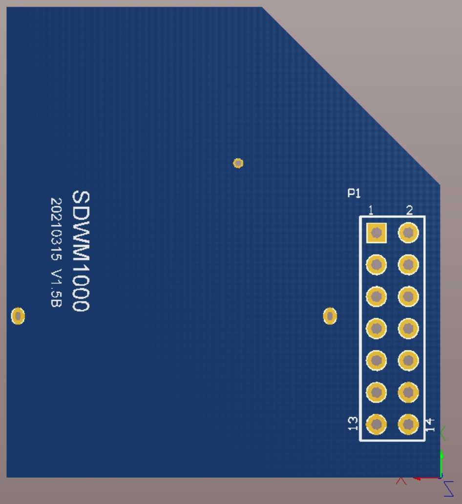
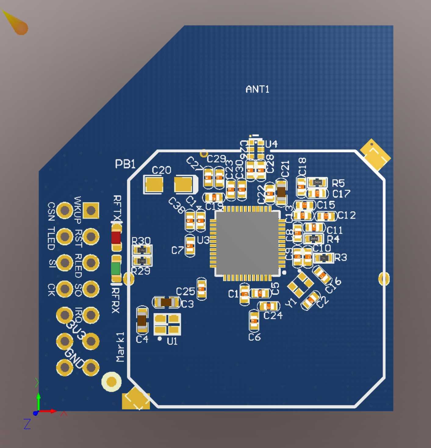
UWB Module SDWM1000 Circuit Diagram and PCB - Price: $300 USD
This is our later mass production module. The module uses a PCB antenna and uses pin headers to connect to the anchor chassis. Can be directly adapted to two models of indoor anchors, A1102P and A1106P.
This module has basically the same circuit as the original DWM1000 and has no extra functions. Please note that LNA and PA are not added .
We have tested that when using 850K rate, the longest communication distance is about 200 meters to 300 meters .
Someone may wonder why the module circuit is more expensive than the anchor backboard circuit?
Because of the difficulty! Hardware engineers know that in most cases, digital circuits are simpler than analog circuits.
Although we have modified the chassis of the single network port anchor dozens of times, the changes are all in details. It cannot be said to be worthless, but it is not strictly necessary.
In the early days, in order to reduce the difficulty of research and development, we always used the original UWB module. As the product matured and we hoped to reduce production costs, we decided to develop our own UWB module. The difficulty in developing UWB modules mainly lies in wiring. The wiring of the RF circuit is not just about impedance matching. This has always been a technical job, which requires not only theoretical support but also empirical support. We tried it many times before we got a satisfactory result. You can think about it, how long does it take a qualified engineer who is proficient in RF wiring to figure this thing out? How much salary are you going to pay him? For this price, it's just free of charge.
If you need a module with longer communication distance, please click here: UWB Module UM2000 Circuit Diagram and PCB - Price: $450 USD or UWB Module Anchor-RFM-PA-LNA-ANT Circuit Diagram and PCB - Price: $450 USD
- Details
- Written by: zhang
- Category: Sales
UWB Location Dual Network Port Anchor A1106P BackBoard Circuit Diagram and PCB Diagram - Price: $300 USD
A1106P is based on our best-selling anchor A1102P, which adds a network switch chip and a POE power supply chip. It can connect multiple anchors in series to save wiring costs and POE switch ports.
Use STM32F103RET6 as the main control MCU, W5500 as the network interface, TPS23753APW as the POE power receiver, MAX5980 as the POE power supply chip, and IP175 network switch chip.
Please note that only AD project files are provided, and there is no STM32 firmware source code. If you need the firmware source code, please click here: UWB Location Anchor Firmware Source Code - Price: $7,500 USD
We provide the following 6 versions of AD project files:
├─SCH-AnchorV-POE V3.0-打样
│  ├─pcb
│  └─sch
├─SCH-AnchorV-POE V3.1-打样
│  ├─pcb
│  └─sch
├─SCH-AnchorV-POE V3.2-打样
│  ├─pcb
│  └─sch
├─SCH-AnchorV-POE V3.3-量产一次
│  ├─pcb
│  └─sch
├─SCH-AnchorV-POE V3.4(TI-UWB原厂模块,仅打样)
│  ├─pcb
│  └─sch
└─SCH-AnchorV-POE V3.5-批量量产
    ├─pcb
    └─sch
Please note that this sales item only includes the anchor backboard and does not include UWB module circuits. If you use the original DWM1000 module, we can provide the adapter board PCB diagram.
If you want to produce UWB modules by yourself, we have 3 types of UWB modules for you to choose from.
UWB Module SDWM1000 Circuit Diagram and PCB - Price: $300 USD
UWB Module Anchor-RFM-PA-LNA-ANT Circuit Diagram and PCB - Price: $450 USD
UWB Module UM2000 Circuit Diagram and PCB - Price: $450 USD