• Product Overview

    The A101 is a high-precision Real-Time Locating System (RTLS) anchor utilizing Ultra-Wideband (UWB) wireless communication technology. Featuring a sleek ceiling-mount industrial design, it is optimized for high-precision indoor positioning across various sectors. The system supports the TDOA architecture, delivering a typical positioning accuracy of 10–30 cm.

    The A101 offers exceptional architectural flexibility, functioning as either a synchronization transmitter for Downlink TDOA or a receiving terminal for Uplink TDOA. In Downlink mode, the A101 supports autonomous offline operation, significantly reducing dependency on network infrastructure.

    Key Features

    1. Dual-Mode Support: Compatible with both Uplink and Downlink TDOA architectures to meet diverse business requirements.

    2. Precision Clock Synchronization: Utilizes proprietary synchronization technology to maintain a time error between anchors of less than 0.6 ns, ensuring centimeter-level stability.

    3. Flexible Networking: Equipped with built-in Wi-Fi; supports autonomous offline operation when configured as a Downlink TDOA anchor.

    4. Simplified Deployment: Features a standard USB Type-C 5V power interface, compatible with common 5V/1A power adapters to simplify onsite wiring.

    5. Smart Management: Supports USB HID for initial local configuration and network-based remote parameter tuning.

    6. IP Management: Supports both DHCP for automatic IP allocation and static IP assignment.

    7. Auto-Discovery: Capable of automatic discovery by the positioning engine.

    8. Standards Compliance: Each device features a unique EUI-64 ID; supports PAN ID filtering to exclude irrelevant UWB packets; fully compliant with IEEE 802.15.4-2011 standards.

    9. Advanced RF Tuning: Configurable UWB parameters including preamble length, PRF, and PAC to adapt to complex multi-path environments.

    10. Maintenance & Monitoring: Supports Over-the-Air (OTA) firmware updates; features an integrated status LED with adjustable brightness.


    Technical Specifications

    Category Item Specification
    Physical Specs Dimensions 73mm × 73mm × 30mm
    Power Input Voltage / Consumption 5V DC / < 1W
    Environment Operating Temp / Humidity -10°C to 60°C / 0% to 70% RH (Non-condensing)
    UWB RF Supported Channels Channel 5 / Channel 9
      Data Rate 850Kbps / 6.8Mbps
      Max Range Up to 100 meters (Line-of-Sight)
      Transmit Power < -85 dBm/MHz
    Connectivity Network Type Wi-Fi (DHCP / Static IP supported)
    Interface Communication USB Type-C (HID Protocol supported)


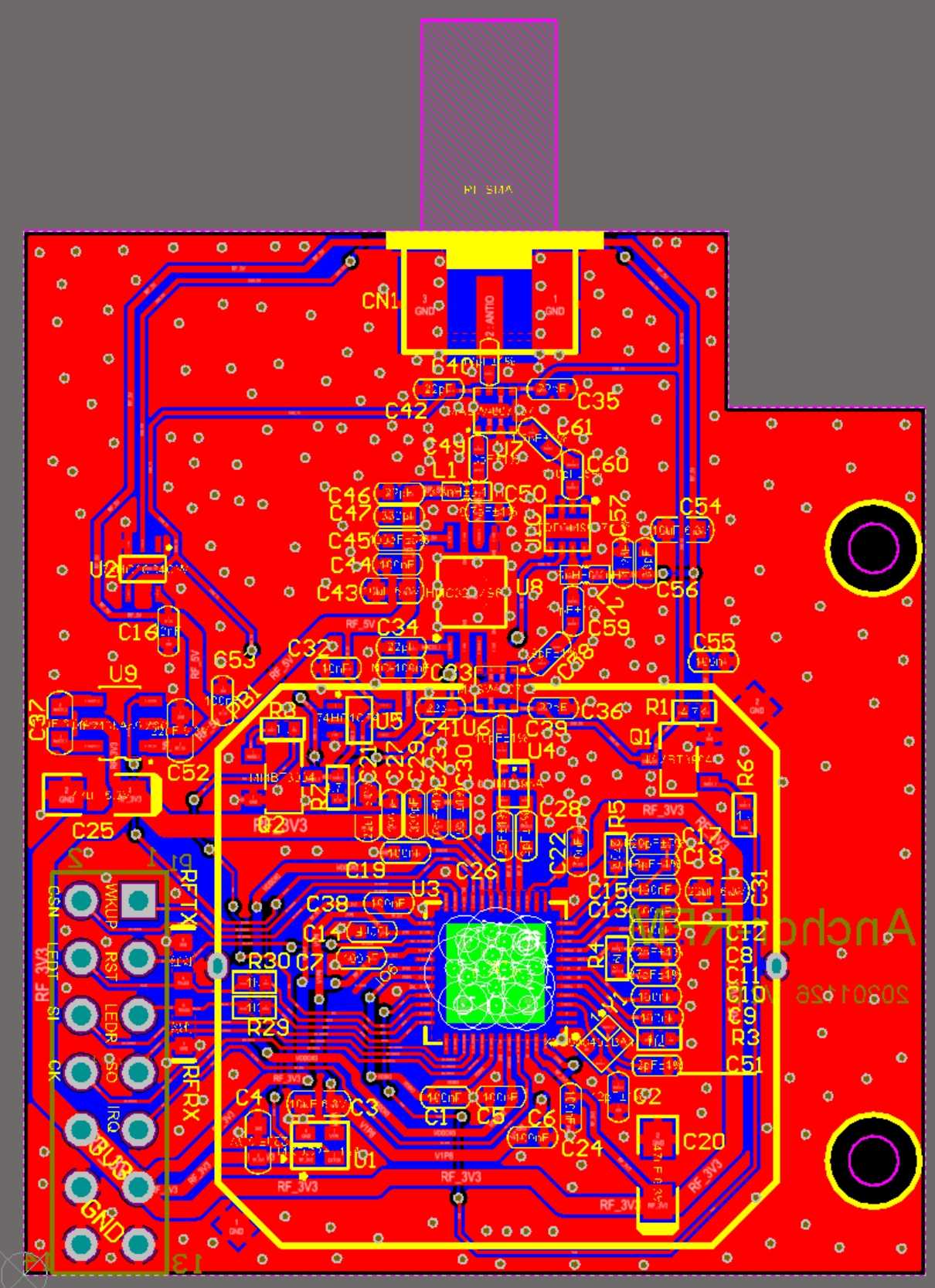
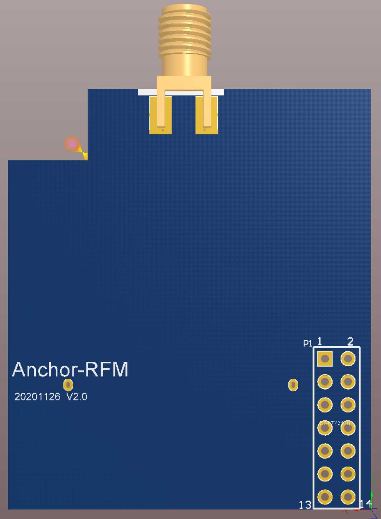
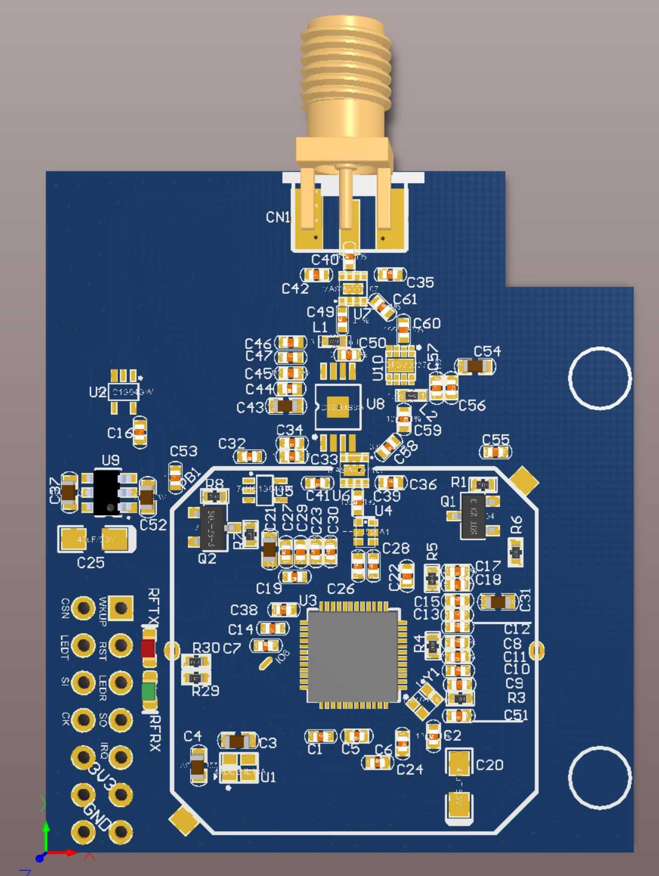
UWB Module UM2000 Circuit Diagram and PCB - Price: $450 USD

The module adds LNA and PA, and the communication distance is greatly increased. The module uses an SMA interface, so a separate external antenna is required, and a pin header is used to connect it to the anchor chassis. Can be adapted to outdoor version anchor.

We have tested that when using the 850K rate, the communication distance is more than 800 meters, and it should be further. Due to limited conditions, we did not test longer distances.

UM2000
UM2000
UM2000
UM2000
UM2000
UM2000

Click here to download UM2000 specification manual V1.1.pdf

Someone may wonder why the module circuit is more expensive than the anchor backplane circuit? 

Because of the difficulty! Hardware engineers know that in most cases, digital circuits are simpler than analog circuits.

Although we have modified the chassis of the single network port anchor dozens of times, the changes are all in details. It cannot be said to be worthless, but it is not strictly necessary.

In the early days, in order to reduce the difficulty of research and development, we always used the original UWB module. As the product matured and we hoped to reduce production costs, we decided to develop our own UWB module. The difficulty in developing UWB modules mainly lies in wiring. The wiring of the RF circuit is not just about impedance matching. This has always been a technical job, which requires not only theoretical support but also empirical support. We tried it many times before we got a satisfactory result. You can think about it, how long does it take a qualified engineer who is proficient in RF wiring to figure this thing out? How much salary are you going to pay him? For this price, it's just free of charge.

In the past, after we developed modules without LNA/PA, we started to develop modules with LNA/PA. After all, the coverage area is wide, we can save a lot of anchors, and the total cost of the project can be reduced a lot. But it has always failed. I also bought several finished modules with LNA/PA from TAOBAO for testing. I found that the effect was not very good and the coverage did not increase as much as expected. We also tried using a separate LNA/PA to connect between the antenna and the module, but the effect was not effective either. After many failures and overcoming many pitfalls, I finally achieved a satisfactory result.

If your product has taken shape and is even on sale, then you must be very concerned about coverage. Adding LNA/PA is the only way to solve the problem of coverage.

Copyright

The articles on this site are all original and the copyright belongs to Zhang Xiaolong.

Anyone can reprint, but the source and author information must be indicated.